International Journal of Nanomaterials, Nanotechnology and Nanomedicine
Hydrogen production from sodium borohydride using Co nanoparticles
Rukiye Öztekin and Delia Teresa Sponza*
Cite this as
Öztekin R, Sponza DT (2024) Hydrogen production from sodium borohydride using Co nanoparticles. Int J Nanomater Nanotechnol Nanomed 10(1): 001-007. DOI: 10.17352/2455-3492.000055Copyright License
© 2024 Öztekin R, et. al. This is an open-access article distributed under the terms of the Creative Commons Attribution License, which permits unrestricted use, distribution, and reproduction in any medium, provided the original author and source are credited.In this study, hydrogen [H2(g)] production from sodium borohydride (NaBH4) using cobalt (Co) nanoparticles (NPs) was investigated with a hydrolysis process. Optimum experimental conditions were examined at different hydrolysis times (5, 10, 20, 30, 40, 50, 60, 70, 80, and 90 min), at different hydrolysis temperatures (25, 35, 45, and 65oC), and at increasing Co NPs nanocatalyst concentrations (5, 15 and 30 mg/l) at pH = 13.0, respectively. X-ray diffraction (XRD), Field Emission Scanning Electron Microscopy (FESEM) and Transmission Electron Microscopy (TEM) analyses were performed for characterization studies. H2(g) measurements were made in gaschromatography–mass spectrometry (GC-MS). The maximum 81% H2(g) yield was observed before the hydrolysis process after 90 min, at pH = 13.0, at 25 oC. The maximum H2(g) yields were recorded as 98% after 45 min hydrolysis times at 45 oC, at a pH of 13.0. 99% H2(g) yields were found after 14 min hydrolysis times, at pH a pH of 13.0 at 65 oC. The maximum NaBH4 concentration and using Co NPs concentrations were kept constant at 300 mg/l and 1.5 mg/l, respectively.
Introduction
Hydrogen gas [H2(g)], due to its high energy density and renewable environmental pollution is an environmentally friendly fuel and an efficient energy carrier that reduces dependence on fossil fuels [1]. H2(g) in its purest form, to produce energy; In Proton Membrane Fuel Cell (PEMFC), it is used as fuel with zero greenhouse gas emission output [2]. In traditional H2(g) production methods of converting natural gas to steam, the end products are various greenhouse gases such as carbon monoxide gas [CO(g)] and carbon dioxide gas [CO2(g)]. The source, storage, and safe transport of H2(g) is the key technology for H2(g) use. Main H2(g) production Technologies were H2(g) production by electrolysis, H2(g) production from fossil materials, and biological H2(g) production [3,4].
The main conventional H2(g) storage methods are; compressing or liquefying H2(g) in a tank under pressure [5-7], adsorbing H2(g) using chemicals in intermetallic hydrides [8-10], using activated carbon, carbon nanotubes [11-13] and metal-organic frameworks (MOFs) [14-16].
In recent years, research on the storage of H2(g) with metallic non-metallic hydrides; Compared with traditional H2(g) storage materials, they have very significant advantages [17]. Researchers have investigated many methods of practically storing hydrogen; Storage of hydrogen as chemical hydride is a very promising development [18]. With high H2 value capacity, outstanding stability in alkaline solution, and recycling of by-products, due to its non-flammability and low cost, sodium borohydride (NaBH4) has attracted much attention as a material with desirable properties for H2(g) storage and production [18]. NaBH4 compound for H2(g) storage at ambient temperature and pressure: due to its properties such as high energy density, easy control of H2(g) production rate, stable structure, non-flammable and non-toxic, and others; It is one of the most promising non-metallic hydrides [19-21]. NaBH4, H2(g) storage density, high purity of H2(g) production, and stable hydrolysis process; It is a promising material for high H2(g) storage [22,23]. Hydrolysis of NaBH4 in an alkaline solution is shown in the following equation (Equation 1):
Theoretically, one mole of NaBH4 at 25 oC room temperature may break down into four moles of H2(g) in water with a suitable catalyst present, with four equivalent H atoms originating from the NaBH4 itself and the remaining two moles coming from the breakdown of H2O(aq), as shown in Equation (1). Since the self-hydrolysis of NaBH4 is slow, for practical applications; adding a suitable catalyst ideally, allows a continuous flow of H2(g) from NaBH4 hydrolysis under mild conditions.
The biggest challenge in developing the use of embedded H2(g) within the PEMFC lies in the H2(g) storage system. This traditional way of storing H2(g) in pressure tanks is not suitable for in situ applications as cryogenic liquid H2(aq). Chemical hybrids such as NaBH4, Lithium hydride (LiH), Potassium borohydride (KBH4), Ammonia borane (NH3BH3), and others, they are frequently preferred for hydrogen storage with their high volumetric and high gravimetric H2(g) storage capacities and stability. Pure H2(g) can be produced from these chemical hydrides at room temperature. NaBH4 has been widely accepted as an H2(g) storage source due to its high storage capacity of 10.8% by weight.
Generally, Sodium hydroxide (NaOH), increases the H2(g) production rate of hydrolysis and prevents self-hydrolysis reaction; It is added to the alkaline NaBH4 solution and a catalyst is very necessary to control it. Cobalt (Co) nanocatalysts (NCs) have been widely studied among non-noble metal catalysts [24-26]. On the other hand, the biggest disadvantage of Co NCs is rapid deactivation [26-28]. Cobalt boride (Co-B) is promising for H2(g) production thanks to its high activity and low cost. Particles during Co-B synthesis reduce the effective surface, limiting the area and catalytic activity; agglomeration occurs. Widely accepted mechanism; B-O-based compounds deposited on the Co-B NCs cause the thick passivation layer to deactivate the Co-NCs [28]. Washing with a dilute acid solution or low-temperature calcination can restore the original activity of Co NCs [28-30]. However, Co aggregation and Co leaching were also other causes of deactivation. To improve the stability of Co NCs; there are various strategies. For this, encapsulation of cobalt nanoparticles (Co NPs) in carbon materials is a common method used to prevent agglomeration and leaching of Co NCs [3,4,31,32].
A carbon nanotube (o-CNT) supported Co-B catalyst was prepared and it was determined that the addition of o-CNT supports improved the catalytic activity of the Co NCs with greater Co-B dispersion [33]. For the hydrolysis of NaBH4 in alkaline solutions of carbon-supported Co-B NCs; They reported that activated carbon can provide a high specific surface area and is very stable in an alkaline environment, as a result, it can be used as a potential catalyst [34,35]. The laser ablation synthesis method was studied to produce a thin-film catalyst coupled with Co NPs in a boron matrix with activity comparable to that of the platinum nanocatalysts (Pt-NCs) [36].
In this study, the production of H2(g) from NaBH4 using Co NPs was investigated by hydrolysis process. Optimum experimental conditions were examined at different hydrolysis times (5, 10, 20, 30, 40, 50, 60, 70, 80, and 90 min), at different hydrolysis temperatures (25, 35, 45, and 65 oC), and at increasing Co NPs nanocatalyst concentrations (5, 15 and 30 mg/l) at pH = 13.0, respectively. X-Ray Diffraction (XRD), field emission scanning electron microscopy (FESEM) and transmission electron microscopy (TEM) analyses were performed for characterization studies. H2(g) measurements were made in gas chromatography–mass spectrometry (GC-MS).
Materials and methods
Preparation of Co NCs
Co-B NCs were synthesized according to a procedure described in the literature using n-cetyl-trimethyl-ammonium bromide (CTAB) as the surfactant template [37]. 0.362 mg CTAB was added to an aqueous solution of 0.05 M cobalt chloride (CoCl2) and stirred continuously for 60 min, at 45 °C. After cooling at 25 oC room temperature, 0.24 g NaBH4 was added to the mixture as a reducing agent with continuous stirring. When bubble formation stopped, the remaining solution was filtered; The resulting black powder was thoroughly washed several times with deionized water and then twice with ethanol. The catalyst powder was then transferred to 100 ml of ethanol and the combined mixture was refluxed at 80 °C for 24 h. Next, the refluxed solution was collected and washed three times with ethanol, then dried under a vacuum.
Experimental set-up
To perform catalytic activity measurements; An alkaline stabilized solution of NaBH4 (pH = 13.0, 0.020 ± 0.001 M) (Rohm and Haas) was prepared by adding NaOH. The volume of H2(g) produced during the reaction was measured by applying the gas volumetric method in a suitable glass reaction chamber. The reaction chamber was kept at a constant temperature with an accuracy of ± 0.10 oC using a thermostatic bath. In the experimental setup in the reaction chamber; a catalyst placement device, a pressure sensor, and a mixing system were used. The entire experimental setup is to accurately measure the weight of water displaced by the H2(g) developed during the reaction; combined with an electronic precision balance and completed. The NaBH4 and Co NPs concentrations were kept constant at 300 mg/l and 1.5 mg/l, respectively.
Characterization
X-Ray Diffraction (XRD) analysis: Powder XRD patterns were recorded on a Shimadzu XRD-7000, Japan diffractometer using Cu Kα radiation (λ = 1.5418 Å, 40 kV, 40 mA) at a scanning speed of 1o /min in the 10 - 80o 2θ range. Raman spectrum was collected with a Horiba Jobin Yvon-Labram HR UV-Visible NIR (200 nm - 1600 nm) Raman microscope spectrometer, using a laser with a wavelength of 512 nm. The spectrum was collected from 10 scans at a resolution of 2 /cm. The zeta potential was measured with a SurPASS Electrokinetic Analyzer (Austria) with a clamping cell at 300 mbar.
Field Emission Scanning Electron Microscopy (FESEM) analysis: The morphological features and structure of the experimental samples were determined by Field Emission Scanning Electron Microscopy (FESEM) (FESEM, Hitachi S-4700).
Transmission Electron Microscopy (TEM) analysis: The obtained experimental samples were collected and harvested by centrifugation (8000 rpm, 5 min), washed twice with deionized H2O, resuspended in ethanol (C2H6O), and dripped onto a carbon-coated copper (C-Cu) transmission electron microscopy (TEM) grid. Vacuum drying then occurred to the experimental samples for 24 h at 25oC room temperature. The dry samples on the Cu grid were viewed and examined by TEM Analysis recorded in a JEOL JEM 2100F, Japan under 200 kV accelerating voltage. The size and structure of the experimental samples were identified with TEM analysis.
Gas Chromatography-Mass Spectrometry (GC-MS) analysis: Gaschromatography–mass spectrometry (GC-MS); a Gas Chromatograph (GC) (Agilent Technology model 6890N) equipped with a mass selective detector (Agilent 5973 inert MSD). Mass spectra were recorded using a VGTS 250 spectrometer equipped with a capillary SE 52 column (HP5-MS 30 m, 0.25 mm ID, 0.25 μm) at 220 °C with an isothermal program for 10 min. The initial oven temperature was kept at 50 oC for 1 min, then raised to 220 oC at 25 oC/min and from 200 to 300 oC at 8 oC/min, and was then maintained for 5.5 min. High-purity helium gas [He(g)] was used as the carrier gas at constant flow mode (1.5 ml/min, 45 cm/s linear velocity). All H2(g) measurements of the experimental samples were made in the GC-MS device.
Results and discussions
Characterizations
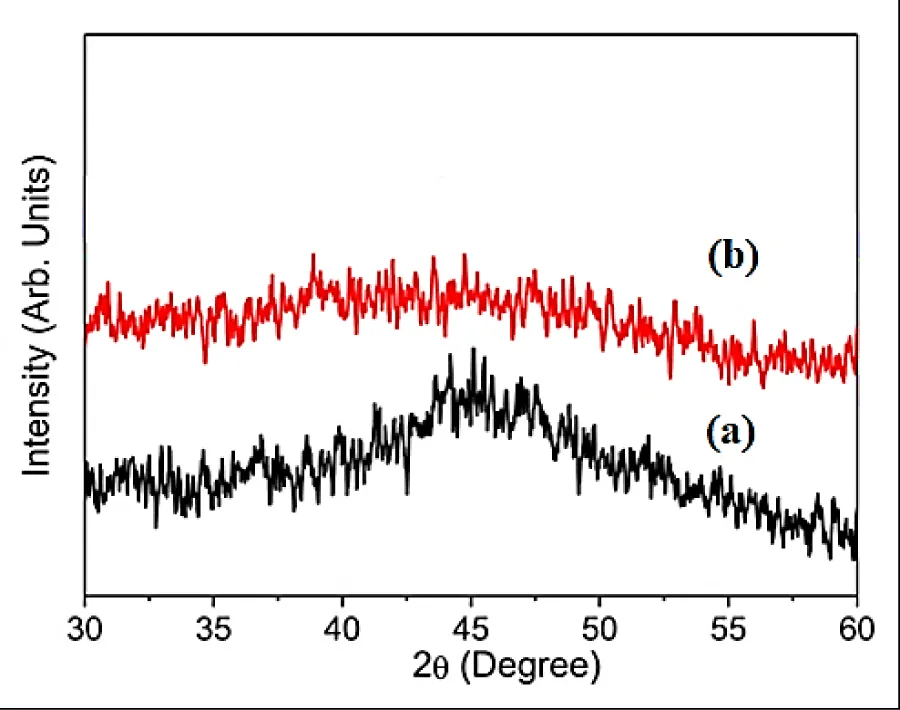
XRD analysis: The results of XRD analysis were investigated after H2(g) production from NaBH4 using Co NPs with hydrolysis process. (Figure 1). The characterization peaks were found at 2θ values of 32.51o, 35.01o, 41.74o, 44.58o, 45.11o, 46.24o, 48.17o, 52.09o, 55.32o and 58.51o, respectively, and which can also be indexed as (101), (210), (204), (312), (121), (200), (104), (103), (201) and (222), respectively (Figure 1a). The characterization peaks were observed at 2θ values of 31.10o, 38.18o, 42.51o, 44.20o, 45.08o, 47.50o, 48.34o, 51.07o, 52.61o, 54.44o, 56.83o and 57.59o, respectively, and which can also be indexed as (104), (203), (101), (210), (204), (312), (115), (301), (142), (100), (205) and (222), respectively (Figure 1b).
The amorphous nature of catalysts with short-range order and long-range disorders are observed in the alloy of Co NPs with the element Boron (B) in the chemical NaBH4 in the form of Co-B. Both of these features were expected to increase the catalytic activity of the Co NPs. Characterization data indicate that the Co NPs used contain NaBH4. The high intensity and sharp diffraction pattern is the crystallinity of NaBH4, while the diffraction pattern which tends to be short or wide is caused by the amorphicity of NaBH4.
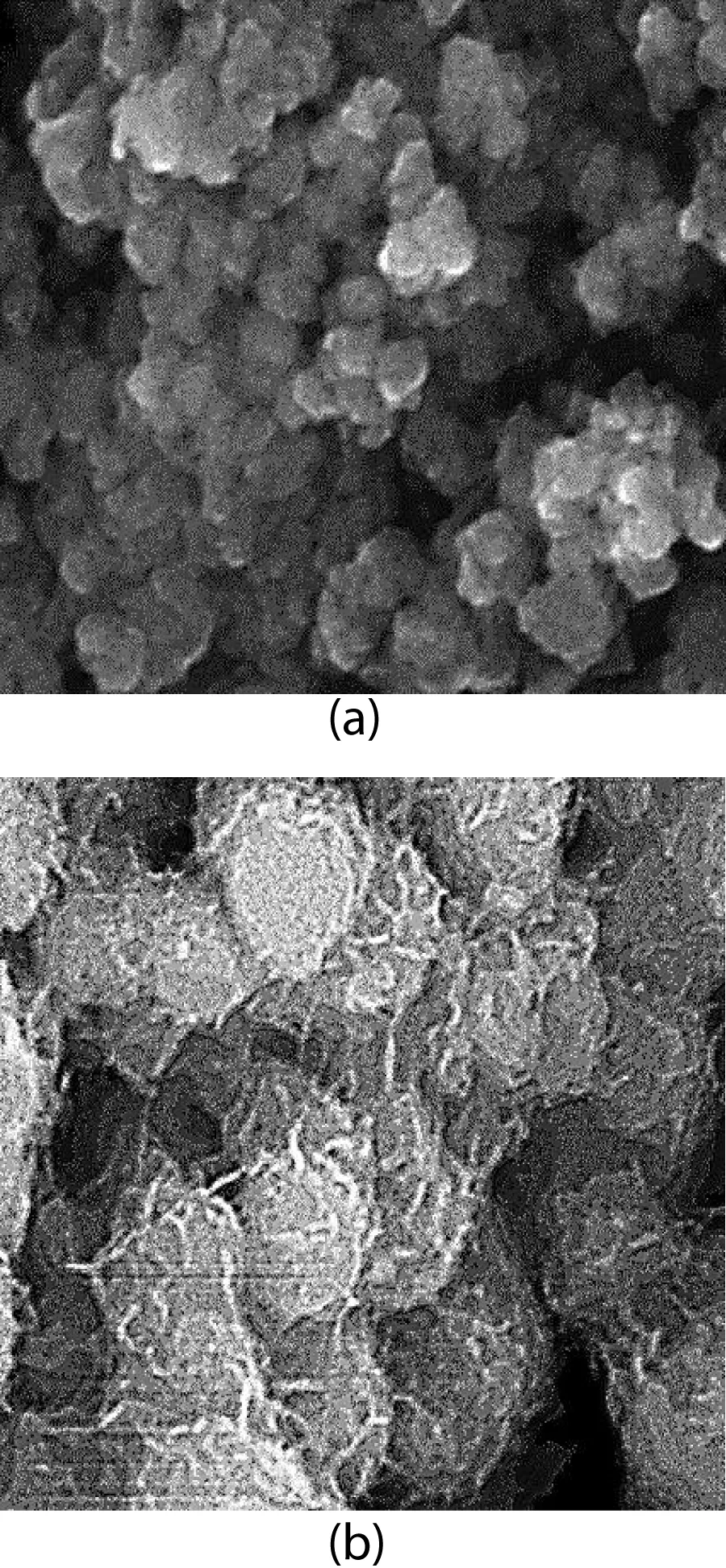
FESEM analysis: The morphological features of Co NPs were characterized through FESEM images before the hydrolysis process (Figure 2a) and after the hydrolysis process (Figure 2b), respectively. SEM images of the Co NP powder sample before (Figure 2a) and after hydrolysis (Figure 2b) for the production of H2(g) from NaBH4 showed that it had an irregularly shaped particle-like morphology and a high degree of agglomeration. The average particle size was measured to be approximately 100 nm; This value is in good agreement with the crystallite size obtained from XRD results. The average particle size was measured to be approximately 100 nm; This value is in good agreement with the crystallite size obtained from XRD results.
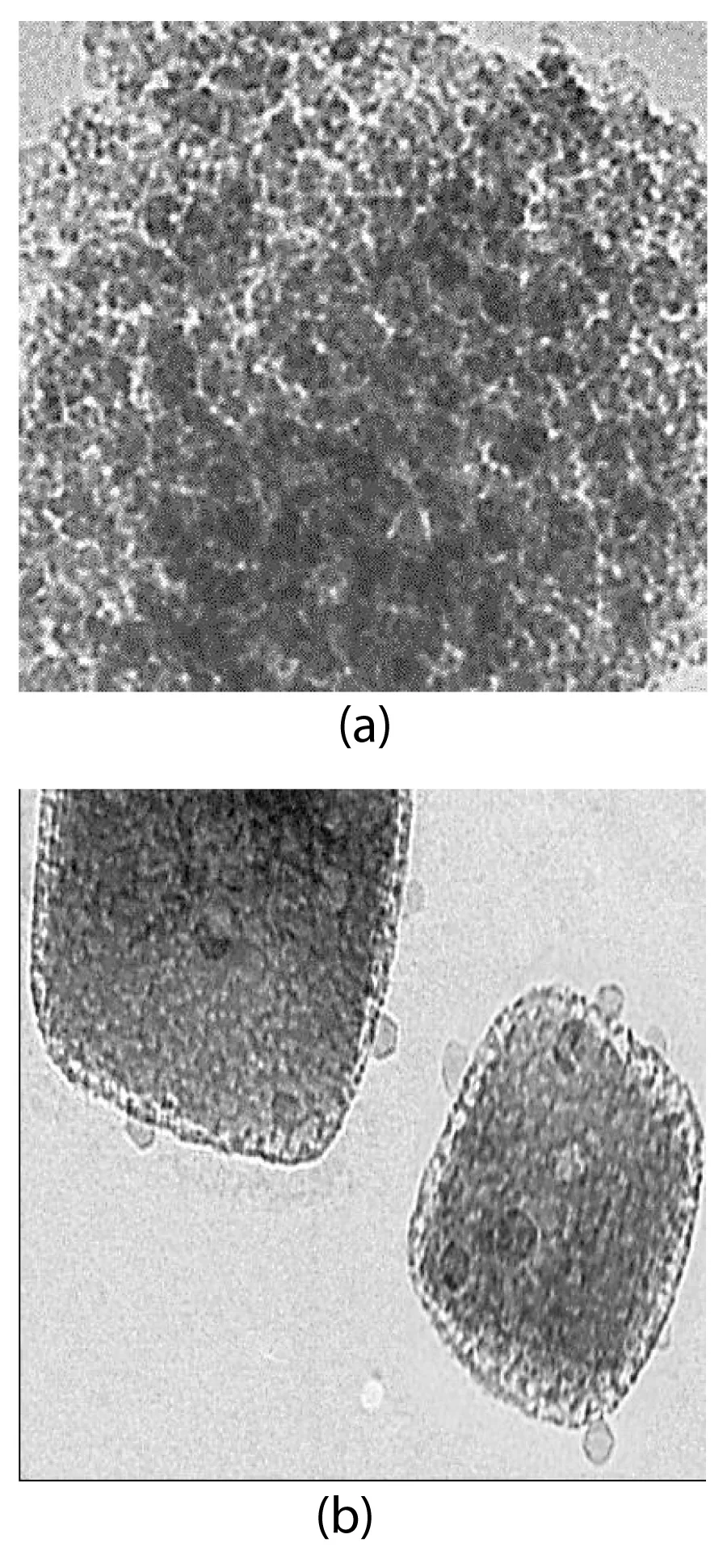
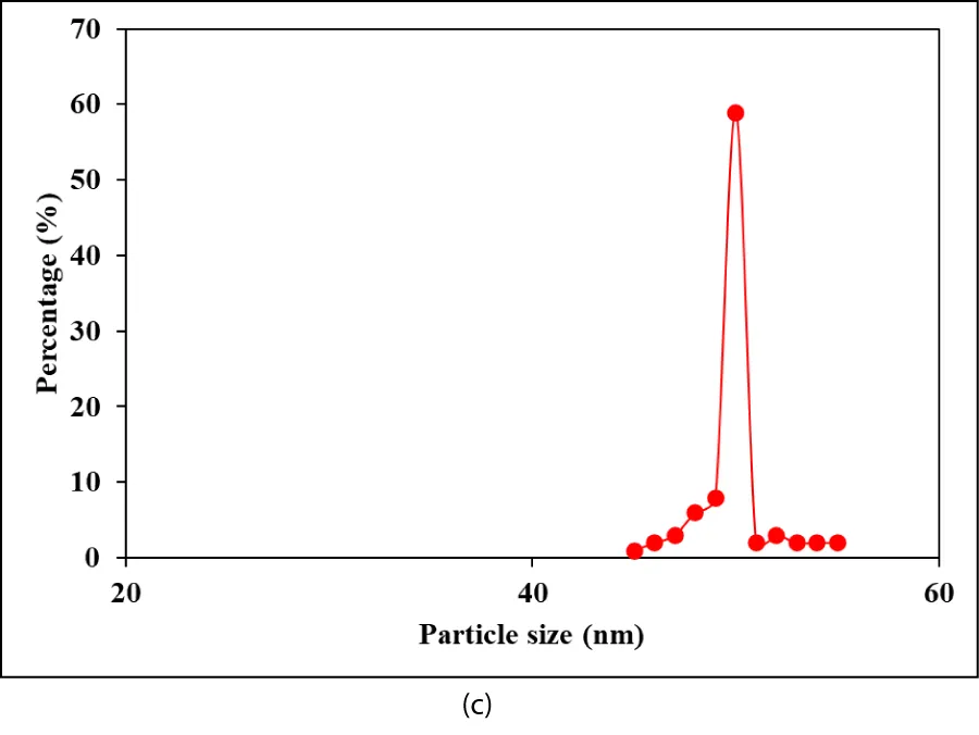
TEM analysis: The TEM images of Co NPs were obtained for H2(g) production from NaBH4 after the hydrolysis process (Figure 3). In the 100 nm size TEM images of Co NPs, the production of H2(g) from NaBH4 was observed after hydrolysis (Figures 3a,3b). A size distribution of Co NPs was performed after the hydrolysis process for the production of H2(g) from NaBH4 (Figure 3c). As clearly seen, Figures 3a,3b confirm that there are no agglomerated Co NPs. TEM images indicate no aggregation of stabilized nanoparticles. Under these conditions, the Co catalyst is highly active in the production of H2(g) from hydrolysis, and it originates from NaBH4.
Particularly, Co NPs were evenly dispersed on the surface of NaBH4 without obvious agglomeration. The average particle size of Co NPs was determined to be 40 and 55 nm, respectively (Figure 3c).
Hydrolysis mechanism of NaBH4 with Co NPs for H2(g) production
CoCl2 aqueous solution reacts with NaBH4 resulting in the formation of catalytically active Co-B NCs [24,38] (Equation 2):
Co-NPs displayed a promoting effect on the hydrolysis reaction of NaBH4. The catalyst may be synthesized in situ during the hydrolysis. For example, the CoCl2 aqueous solution reacts with NaBH4 resulting in the formation of catalytically active cobalt boride (Co2B), which appears as a black precipitate in the aqueous solution [38].
Reaction kinetics of H2(g) production from NaBH4 using Co NPs
During the hydrolysis reaction, the concentrations of both catalyst and NaOH remain constant; however, the concentration of NaBH4 decreases with hydrolysis time as H2(g) increases. This decreasing change in NaBH4 concentration can give us an estimate of the reaction order relative to NaBH4 [39].
For a zero-order reaction, the production volume of H2(g) shows a linear variation as a function of time, as given in Equation 3:
Where; ko: is the rate constant of the zero-order reaction. In the case of first-order reaction, the H2(g) production volume as a function of time has an exponential dependence as given in Equation 4:
Where; : is the initial molar concentration of NaBH4 in the solution and k1: is the overall rate constant of the first-order reaction, respectively.
Effect of increasing hydrolysis times for the H2(g) production from NaBH4 using Co NPs
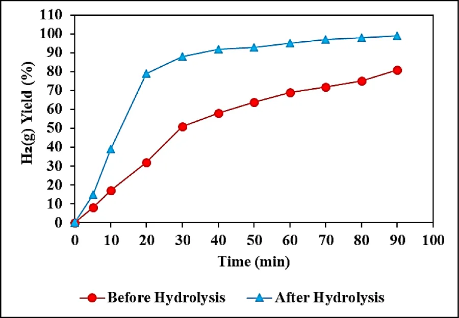
The effects of increasing hydrolysis times (5, 10, 20, 30, 40, 50, 60, 70, 80, and 90 min) on H2(g) production from NaBH4 were investigated before and after the hydrolysis process, at pH = 13.0 and at 25 oC. (Figure 4). 45 kJ/mol activation energy for Co NPs was observed after 90 min hydrolysis time, at pH = 13.0 and 25 oC, respectively (data not shown). 8%, 17%, 32%, 51%, 58%, 64%, 69%, 72%, and 75% H2(g) yields were measured before the hydrolysis process after 5, 10, 20, 30, 40, 50, 60, 70 and 80 min, respectively, at pH = 13.0 and at 25 oC (Figure 4). The maximum 81% H2(g) yield was observed after the 90-minute hydrolysis process at pH = 13.0, at 25 oC (Figure 4). 15%, 39%, 79%, 88%, 92%, 93%, 95%, 97%, and 98% H2(g) yields were measured after the hydrolysis process, after 5, 10, 20, 30, 40, 50, 60, 70 and 80 min hydrolysis times, respectively, at pH = 13.0 and at 25 oC (Figure 4). The maximum H2(g) yield was obtained as 98% after 90 min hydrolysis time at pH = 13.0, at 25 oC (Figure 4).
The H2(g) production percentage was higher after the hydrolysis process compared to the not hydraulized conditions and this yield increased up to 98% as the time was increased from 10 min up to 90 min at 25 oC.
Effect of increasing hydrolysis temperatures for the H2(g) production from 300 mg/l NaBH4 using 1.5 mg/l Co NPs
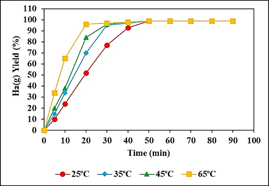
The hydrolysis temperatures were increased from 25 oC to 35, 45, and 65 oC to detect the H2(g) production from NaBH4 using Co NPs, at pH = 13.0 (Figure 5). 98% H2(g) production yields were measured at 25 oC, after 49 min hydrolysis times at pH = 13.0 (Figure 5). The H2(g) yields were 98% at 35oC, after 30 min hydrolysis times at pH = 13.0 (Figure 5). The maximum H2(g) yields were detected as 98% after 45 min hydrolysis times at 45 oC, at a pH of 13.0 (Figure 5). 99% H2(g) yields were found after 14 min hydrolysis times, at pH a pH of 13.0 at 65oC (Figure 5). By increasing of temperature from 25 oC to 65 oC the time required to reach the maximal H2(g) production decreased from 49 min to 14 min. In other words, the increase in temperature decreased the time required to attain the maximum H2(g) production.
As aforementioned with increasing reaction temperature, the reaction time for stoichiometric H2(g) production decreased. A plausible explanation for this observation is the increasing mobility of NaBH4 molecules. Under these conditions, a greater number of realistic collisions beyond the energy threshold barrier occurred [40].
Effect of increasing Co NPs concentrations for the H2(g) production from NaBH4 using Co NPs
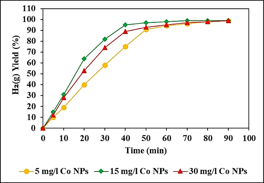
The effects of increasing Co NPs catalyst concentrations (5, 15, and 30 mg/l) on the yields of H2(g) production were examined from NaBH4 using Co NPs, at pH = 13.0, at 65 oC (Figure 6). 95% H2(g) yields were measured for 5 mg/l Co NPs, after 50 min hydrolysis times, at pH = 13.0, at 65oC (Figure 6). 99% H2(g) yields were obtained for 15 mg/l Co NPs, after 50 min hydrolysis times, respectively, at pH = 13.0, at 65oC (Figure 6). 97% H2(g) yields were observed for 30 mg/l Co NPs, after 50 min hydrolysis times, respectively, at pH = 13.0, at 65 oC (Figure 6). The maximum 99% H2(g) yield performance was detected at a Co NP concentration of 15 mg/l, after 50 min hydrolysis times, at pH = 13.0 and at 65 oC (Figure 6).
Hydrogen generation increases as the amount of catalyst increases from 5 mg /l to 100 mg/l, implying that the hydrogen generation rate can be determined by controlling the catalyst amount in the reactor. The optimum catalyst dose for maximum H2(g) yield was chosen as 15 mg /l since the increase in Co NPs loading may cause the enlargement of Co particles, resulting in a reduction in the number of active sites per unit of Co NPs. Previous literature has reported that Co NPs serve as the active site for hydrogen production through the hydrolysis of NaBH4. It has been suggested that the decreased proportion of Co during low-temperature reduction could potentially explain the reduced activity in H2(g) production.
H2(g) generation was limited by the amount of the catalyst [41,42]. Because of the larger surface area and subsequently more active site for hydrolysis of NaBH4 solution by Co-B powder, a fast and easier photocatalytic reaction occurred. Theoretically, a higher concentration of NaBH4 is desired to achieve high hydrogen capacity, but is limited by the solubility limitation of NaBH4 itself and its hydrolysis product namely NaBO2 was accumulated in water. There was no increase in H2(g) production efficiency when the Co NPs concentration increased to 2.5 mg/l.
When the NaBH4 concentration increases from 300 mg/l to 400 mg/l the H2(g) generation rate increases and then decreases. The probable cause of this is the effect of mass and heat transfer during the reaction. However, NaBO2 concentration increases with increasing NaBH4 concentration solution and this leads to an increase in solution viscosity when the NaBH4 concentration is 400 mg/l. The increase in viscosity does not lead to limitations of the mass transfer only from the NaBH4 solution to the inner surface of the catalysts. At the same time, NaBO2 concentration may exceed the solubility limit. NaBO2 can precipitate and inhibit the active site on the catalyst surface. Thus, it prevents contact with BH4 and subsequent hydrolysis rate. The reason behind this is that, initially, at lower concentrations of NaBH4, the contact time between BH4− ions and the catalyst is higher. As the concentration of NaBH4 increases, the formation of some by-products can be elevated and it probably blocks the reactive sites of the catalyst, thus increasing the viscosity of the solution and lowering the H2(g) generation rate.
Conclusion
An increase of temperature from 25 oC to 65 oC decreased the duration necessary to reach the maximum H2(g) production with a percentage of 98% after hydrolysis from 300 mg/l NaBH4 at a Co NPs concentration of 1.5 mg/l after 14 min. XRD spectra showed the amorphous nature of catalysts with the short and long-range disorder observed in the alloy of Co NPs. SEM images of the Co NPs powder sample exhibited irregularly shaped particle-like morphology. TEM images show that the stabilized nanoparticles do not aggregate.
Co-NPs displayed a promoting effect on the hydrolysis reaction of NaBH4. Co NPs catalyst showed good stability in the production of H2(g) from NaBH4.
Experimental analyses in this study were performed at the Laboratories of the Canada Research Center, Ottawa, Canada. The authors would like to thank this body for providing financial support.
- Tao K, Arano H, Zhang PP, Ai PP, Han L, Tsubaki N. Enhanced hydrogen production from steam reforming of vegetable oil over bimodal ZrO2-SiOM2 supported Ni catalyst. Chemistry. 2017; 2:527-532.
- Johnston B, Mayo MC, Khare A. Hydrogen: the energy source for the 21st century. Technovation. 2005; 25:569-585.
- Ouyang LZ, Cao ZJ, Wang H, Hu RZ, Zhu M. Application of dielectric barrier discharge plasma-assisted milling in energy storage materials-a review. Journal of Alloys and Compounds. 2017; 691:422-435.
- Ouyang LZ, Chen W, Liu JW, Felderhoff M, Wang H, Zhu M. Enhancing the regeneration process of consumed NaBH4 for hydrogen storage. Advanced Energy Materials. 2017; 7:1700299.
- Ogden JM, Kreutz TG, Steinbugler MM. Fuels for fuel cell vehicles. Fuel Cells Bulletin. 2000; 3(16):5-13.
- Zheng J, Kai F, Liu Z, Chen C, Ma X. Lightweight highpressure hydrogen tank. Journal of Chemical Industry and Engineering. 2004; 55:130-133.
- Zuttel A. Materials for hydrogen storage. Materials Today. 2005; 6(9):24-33.
- Schlapbach L, Züttel A. Hydrogen-storage materials for mobile applications. Nature. 2001 Nov 15;414(6861):353-8. doi: 10.1038/35104634. PMID: 11713542.
- Yuan XX, Xu NX. Determination of hydrogen diffusion coefficient in metal hydride electrode by cyclic voltammetry. Journal of Alloys and Compounds. 2001; 316:113-117.
- Yuan XX, Xu NX. Electrochemical and hydrogen transport kinetic performance of MlNi3.75Co0.65Mn0.4Al0.2 metal hydride electrode at various temperatures. Journal of the Electrochemical Society. 2002; 149(4):A407-A413.
- Noh JS, Agarwal RK, Schwarz JA. Hydrogen storage systems using activated carbon. International Journal of Hydrogen Energy. 1987; 12:693-700.
- Dillon AC, Jones KM, Bekkedahl TA, Kiang CH, Bethune DS, Heben MJ. Storage of hydrogen in single-walled carbon nanotubes. Nature. 1997; 386:377-379.
- Atkinson K, Roth S, Hirscher M, Grunwald W. Carbon nanostructures: an efficient hydrogen storage medium for fuel cells. Fuel Cells Bulletin. 2001; 38:9-12.
- Rosi NL, Eckert J, Eddaoudi M, Vodak DT, Kim J, O'Keeffe M, Yaghi OM. Hydrogen storage in microporous metal-organic frameworks. Science. 2003 May 16;300(5622):1127-9. doi: 10.1126/science.1083440. PMID: 12750515.
- Jia C, Yuan XX, Ma ZF. Research progress of Metal-Organic Frameworks (MOFs) as hydrogen storage materials. Progress in Chemistry. 2009; 21(9):1954-1962.
- Eddaoudi M, Kim J, Rosi N, Vodak D, Wachter J, O'Keeffe M, Yaghi OM. Systematic design of pore size and functionality in isoreticular MOFs and their application in methane storage. Science. 2002 Jan 18;295(5554):469-72. doi: 10.1126/science.1067208. PMID: 11799235.
- Biniwale RB, Rayalu S, Devotta S. Chemical hydrides: a solution to high capacity hydrogen storage and supply. International Journal of Hydrogen Energy. 2008; 33:360-365.
- Abutaleb A, Maafa IM, Zouli N, Yousef A, El-Halwany MM. Electrospun Co Nanoparticles@PVDF-HFP Nanofibers as Efficient Catalyst for Dehydrogenation of Sodium Borohydride. Polymers (Basel). 2023 Jan 24;15(3):597. doi: 10.3390/polym15030597. PMID: 36771898; PMCID: PMC9920680.
- Wee JH, Lee KY, Kim SH. Sodium borohydride as the hydrogen supplier for proton exchange membrane fuel cell systems. Fuel Process Technology. 2006; 87(9):811-819.
- Krishnan P, Hsueh KL, Yim SD. Catalysts for the hydrolysis of aqueous borohydride solutions to produce hydrogen for PEM fuel cells. Applied Catalyst B: Environmental. 2007; 77(1-2): 206-214.
- Zhang JS, Zheng Y, Gore JP, Fisher TS. 1 kWe sodium borohydride hydrogen generation system: part I: experimental study. Journal of Power Sources. 2007; 165(2): 844-853.
- Chen Y, Kim H. Preparation and application of sodium borohydride composites for portable hydrogen production. Energy. 2010; 35:960–963.
- Chinnappan A, Kang HC, Kim H. Preparation of PVDF nanofiber composites for hydrogen generation from sodium borohydride. Fuel Processing Technology. 2011; 92:1368–1373.
- Wu C, Wu F, Bai Y, Yi BL, Zhang HM. Cobalt boride catalysts for hydrogen generation from alkaline NaBH4 solution. Materials Letters. 2005; 59:1748-1751.
- Ozerova AM, Simagina VI, Komova OV, Netskina OV, Odegova GV, Bulavchenko OA, Rudina NA. Cobalt borate catalysts for hydrogen production via hydrolysis of sodium borohydride. Journal of Alloys and Compounds. 2012; 513:266-272.
- Demirci UB, Miele P. Cobalt-based catalysts for the hydrolysis of NaBH4 and NH3BH3. Phys Chem Chem Phys. 2014 Apr 21;16(15):6872-85. doi: 10.1039/c4cp00250d. Epub 2014 Mar 10. PMID: 24615471.
- Muir SS, Yao X. Progress in sodium borohydride as a hydrogen storage material: development of hydrolysis catalysts and reaction systems. International Journal of Hydrogen Energy. 2011; 36:5983-5997.
- Arzac GM, Hufschmidt D, De Haro MCJ, Fernandez A, Sarmiento B, Jimenez MA, Jimenez MM. Deactivation, reactivation and memory effect on Co-B catalyst for sodium borohydride hydrolysis operating in high conversion conditions. International Journal of Hydrogen Energy. 2012; 37:14373-14381.
- Liang Y, Wang P, Dai HB. Hydrogen bubbles dynamic template preparation of a porous Fe-Co-B/Ni foam catalyst for hydrogen generation from hydrolysis of alkaline sodium borohydride solution. Journal of Alloys and Compounds. 2010; 491:359-365.
- Zhuang DW, Dai HB, Zhong YJ, Sun LX, Wang P. A new reactivation method towards deactivation of honeycomb ceramic monolith supported cobalt-molybdenum-boron catalyst in hydrolysis of sodium borohydride. International Journal of Hydrogen Energy. 2015; 40:9373-9381.
- Ouyang LZ, Cao ZJ, Li LL, Wang H, Liu JW, Min D, Chen YW, Xiao FM, Tang RH, Zhu M. Enhanced high-rate discharge properties of La11.3Mg6.0 Sm7.4 Ni61.0Co7.2Al7.1with added graphene synthesized by plasma milling. International Journal of Hydrogen Energy. 2014; 39:12765-12772.
- Ouyang LZ, Guo LN, Cai WH, Ye JS, Hu RZ, Liu JW, Yang LC, Zhu M. Facile synthesis of Ge@ FLG composites by plasma assisted ball milling for lithium ion battery anodes. Journal of Materials Chemistry A. 2014; 2:11280-11285
- Li F, Li Q, Kim H. CoB/open-CNTs catalysts for hydrogen generation from alkaline NaBH4 solution. Chemical Engineering Journal. 2012; 210:316–324.
- Niu W, Ren D, Han Y, Wu Y, Gou X. Optimizing preparation of carbon supported cobalt catalyst for hydrogen generation from NaBH4 hydrolysis. Journal of Alloys and Compounds. 2012; 543:159–166.
- Shih YJ, Su CC, Huang YH, Lu MC. SiO2-supported ferromagnetic catalysts for hydrogen generation from alkaline NaBH4 (sodium borohydride) solution. Energy. 2013; 54:263-270.
- Patel N, Miotello A, Bello V. Pulsed laser deposition of Conanoparticles embedded on B-thin film: a very efficient catalyst produced in a single step process. Applied Catalysis B: Environmental. 2011; 103:31-38.
- Dong-ge T, Wei C, Yong-yue L, Hong C, Xiao-yang J. Preparation and characterization of amorphous Co-B catalysts with mesoporous structure. Journal of Molecular Catalysis A: Chemical. 2007; 269:149-157.
- Levy A, Brown JB, Lyons CJ. Catalyzed hydrolysis of sodium borohydride. Industrial & Engineering Chemistry Research. 1960; 52:211-214.
- Patel N, Fernandes R, Miotello A. Hydrogen generation by hydrolysis of NaBH4 with efficient Co-P-B catalyst: a kinetic study. Journal of Power Sources. 2009; 188:411-420.
- Xu J, Du X, Wei Q, Huang Y. Efficient hydrolysis of sodium borohydride by Co-B supported on nitrogen-doped carbon. ChemistrySelect. 2020; 5(22):6683–6690.
- Dönmez F, Ayas N. Synthesis of Ni/TiO2 catalyst by sol-gel method for hydrogen production from sodium borohydride. International Journal of Hydrogen Energy. 2021; 46:29314–29322.
- Farrag M, Ali GAM. Hydrogen generation of single alloy Pd/Pt quantum dots over Co3O4 nanoparticles via the hydrolysis of sodium borohydride at room temperature. Sci Rep. 2022 Oct 11;12(1):17040. doi: 10.1038/s41598-022-21064-z. PMID: 36220869; PMCID: PMC9553983.

Article Alerts
Subscribe to our articles alerts and stay tuned.
 This work is licensed under a Creative Commons Attribution 4.0 International License.

 Save to Mendeley
